
|
nfg.2y.net Games Division Note: The images and information on this page are free to use but please link to this page if you do! |
||||||
|
The X68000 series of computers from Sharp is pretty amazing. Back in the ST + Amiga days Sharp's Motorola 68000-based computer was running circles around them both, gamewise. There's not really any disputing the case is leagues ahead either. The big drawback is a flaky power supply - they die a lot, and they're not directly compatible with any other unit. Since the X68k used soft-power like your modern PC-compatible you can easily find supplies that will work - but typically they're two or three times larger than you want. Also, you need a couple of small parts to engage a timed poweroff that X68k PSUs employ, but ATX ones dont. One cheap chip and a resistor, some soldering, and you're done. This info applies to all models of X68000. The pictures below are of an operation on an XVI, but there's data below for all models.
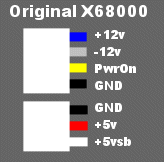
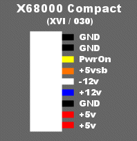
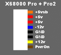
This document is divided into two halves: the theory and the example. The basic plan involves removing the original PSU, and shoving a new (but oviously larger) ATX PSU in its place. There are two gotchas: Gotcha 1: The polarity of the power signal is reversed, so you need an invertor IC (a 74HC04) and a resistor (4.7k Ohm). You'll connect them as shown below. Gotcha 2: The new PSU will take space previously reserved for a harddrive, so if you have an internal HD you're pretty much boned. On the other hand if you didn't already have one you won't be missing out - the X68k used a custom power connector for HDs which you'd probably never find this far into the future, so you're taking space you'd probably never have used anyway. 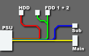 Original Power Wiring Diagram - Simple, no? Now as you can see above there's not much to it. Total connections may differ slightly between models. The Main connector differs between models - there are five kinds of Main connectors (detailed below). Shown below are the connectors you'll find inside your system and on the ATX PSU. Note the wire colours may be duplicated for different functions on the ATX + X68 sides. Don't let that confuse you, you might regret it. Here's the ATX connector - the colours are always the same. Here's what the 7404 circuit looks like, it's really simple. The 'sb' means StandBy power. The PSU is always supplying a little bit of power to the system, and when the PwrOn signal is received it fires up the whole unit.  Simple circuit. The logic above is simple. The 5vsb from the ATX PSU connects to both the chip + the X68k. The resistor connects pin 14 to pin 1, and also to the X68k PowerOn signal. Pin 2 from the chip is inverted and connects to the PowerOn signal from the ATX PSU. The other connectors all carry the same voltages, and you can match them with the voltages from the main ATX connector or the smaller drive connectors. The only voltage you can't get from the smaller connectors is -12v, it's only present on the main ATX connector. As you can see in the image below, the original PSU is an oddly shaped unit custom fit to the system: 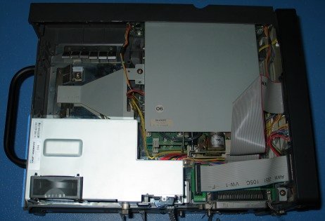 The old CPU (hilighted) First remove the old supply. This is pretty easy - it's held in by three large screws, and once removed the whole PSU just kind of falls out, except that it's attached to the system. Open the PSU and disconnect the AC power internally, the black and white wires connected to the power PCB can be easily removed. Cut all the wires running from the PSU to the X68k, as close to the PCB as you can (more wire is easily to work with). Keep the top shell of the PSU, and throw away the bottom part with the PCB + thick aluminum case. You should end up with something like this: 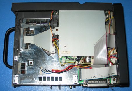 The old PSU is gone. Loose wires were cut from inside the PSU. You have two options: You can install a new slim ATX PSU (about $50 in Akihabara, YMMV) or you can use an ugly external box with wires running into the case. If you chose the latter, ignore this next step. You'll need to cut the top shell to accomodate your new PSU, and you'll need a dremel or other cutting tool. I made only one cut, vertical near the center, and did a quick grind left to right across the top corner, making it very easy to bend back and forth until it popped off, leaving a clean cut. This panel isn't joined on the right side, so there's no cutting required. The PSU I chose had two mounting holes, so I drilled two matching holes in the top of the shell so it could be bolted on. 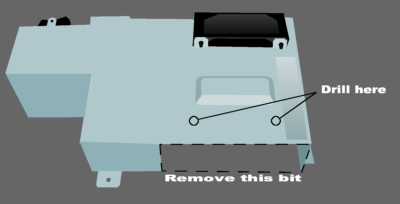 In the next picture I was sizing up the fit, making sure I had room to route the cables, etc. As you can see it was pretty much a perfect fit. For the record I used a Seventeam micro-ATX PSU. (I'll put the model # here as soon as I find the box).  This image shows the nearly complete transplant, with the new ATX PSU in place and all the wires soldered together. One of the green heat-shrink blobs contains the chip and resistor, the other holds together a handful of loose wires I didn't need floating around. There's a lot of unused wire in there, the ATX PSU had connectors and wiring for six drives, and I didn't need those at all (though for convenience I used one). You can safely cut them back as far as the PSU itself, to simplify wiring.  In order to get power to the new PSU I pulled the AC socket out of the ATX unit and removed the connector, and soldered those wires directly to the black + white ones coming from the original power switch. This means the original external power switch still works as planned. Also I connected the original fan to 12v from the ATX PSU, so it spins as loudly as ever. Without this the ATX unit can't shove air out of the case, so it gets REAL HOT. I tried adding a plastic funnel instead, but only the original fan could move enough air.  As a final step the large unused bracket was bent into a zig-zag shape so that it would apply pressure to the new ATX PSU, holding it in place, as well as be mounted as it originally was. Between this bracket and the two screws in the original PSU cover the new PSU is held very firmly in place. That's it!  |




|
||||||
