Title: Universal RGB Amp PCBs - Interest check
Post by: BlueBMW on March 15, 2012, 01:00:41 PM
Post by: BlueBMW on March 15, 2012, 01:00:41 PM
Hello all, I've done some RGB mods in the past using transistors and NJM2267 chips, and they work fine, but then I was informed of the THS7315 which seems to do wonders in a very small package! I've done some prototyping using a PC Engine Duo-R and a friend and I have come up with a PCB design to utilize this amp chip.
I'm looking to get these PCBs made up in the next month or two. What interest would there be in these and does anyone have any design change recommendations?
Also, what sort of price would be considered fair for a pre-built board like this?
Approx 1.125" x 1.375" - probably a 0.031" thick PCB, but might be 0.0625"
Trimmers are 10K ohms, Q1 is the THS7315, Q2 is an LM1881, all the caps are 0603 0.1uf except c5 which is a 1206 22uf, R1 - R3 are 75 ohm
The sync on green / sync stripper part of the board do not have to be installed / utilized in every application.
I'll be moving the text to the left and adding a mounting hole to the design.
Title: Re: Universal RGB Amp PCBs - Interest check
Post by: soop on March 20, 2012, 02:52:40 AM
Post by: soop on March 20, 2012, 02:52:40 AM
Hello Blue :D
I'd probably be interested in some of these. Would they be populated? And how much do you think they'd cost? As long as it's not loads, I have about 3 White PC Engines that need a bit of RGB love, and maybe a Core II I could mod.
Building my own amp led to failure, and I haven't had the heart to go back to it.
But if it's not populated, I have the parts, though it looks like you intend to use tantalum caps on that one, right? And I have a bunch of C1815s
Title: Re: Universal RGB Amp PCBs - Interest check
Post by: Artemio on March 23, 2012, 11:16:11 AM
Post by: Artemio on March 23, 2012, 11:16:11 AM
Interested in a few here as well, if you are willing to do some international shipping or ship to a hotel when I visit the US =P
Title: Re: Universal RGB Amp PCBs - Interest check
Post by: BlueBMW on March 23, 2012, 02:00:29 PM
Post by: BlueBMW on March 23, 2012, 02:00:29 PM
I'm doing a little more tweaking / prototyping to make sure I select the best size of trimmer for the application. Once I've got the best possible values for all the parts, I'll look into having the PCBs made up. It usually takes about 3 weeks to get boards in.
As far as populated vs unpopulated, I'd do it however people wanted it. I'll be soldering them by hand, but surface mount on brand new boards / components is not too difficult. Not everyone will want the sync on green or sync stripper circuits. Pricing will be as cheap as possible. Once I find out the total cost etc, I'll figure out the best price for them.
International shipping has never been a problem :)
Title: Re: Universal RGB Amp PCBs - Interest check
Post by: panzeroceania on April 05, 2012, 12:06:41 PM
Post by: panzeroceania on April 05, 2012, 12:06:41 PM
what systems would these be used for? PC Engine mainly? I am interested, I want to support work like this. Any idea on price points?
I need to buy/make an RGB amp for my Sega Mark III.
I would buy one though as I need one for my NEC Supergrafx, I already have one for my Super CD2 but it would be nice to have something for the Supergrafx
I need to buy/make an RGB amp for my Sega Mark III.
I would buy one though as I need one for my NEC Supergrafx, I already have one for my Super CD2 but it would be nice to have something for the Supergrafx
Title: Re: Universal RGB Amp PCBs - Interest check
Post by: BlueBMW on April 11, 2012, 01:29:37 PM
Post by: BlueBMW on April 11, 2012, 01:29:37 PM
Quote from: panzeroceania on April 05, 2012, 12:06:41 PM
what systems would these be used for? PC Engine mainly? I am interested, I want to support work like this. Any idea on price points?
I need to buy/make an RGB amp for my Sega Mark III.
I would buy one though as I need one for my NEC Supergrafx, I already have one for my Super CD2 but it would be nice to have something for the Supergrafx
Primarily I designed these with the NEC consoles in mind, though they could really be used anywhere a signal amplifier is needed. Aside from RGB, they can also be used on NEC consoles to amplify the S-Video signals that the HuC6260 chip generates (pin 40 for Y) and then strip the composite for nice clean S-Video without an external encoder.
Price point isnt set yet... I'm really hoping to be as cheap as possible though. As it is, I'm looking at a parts cost of around $10 a board fully populated. So add in whatever assembly time is worth, shipping / packaging costs and whatever a fair profit is on these, that will be the final price.
Title: Re: Universal RGB Amp PCBs - Interest check
Post by: viletim on April 11, 2012, 10:15:28 PM
Post by: viletim on April 11, 2012, 10:15:28 PM
Quote from: BlueBMW on March 15, 2012, 01:00:41 PM
does anyone have any design change recommendations?
Absolutely!
1. Use a THS7314 instead of a THS7315. It has a gain of only 2 which makes it much better suited as a video driver.
2. Remove the potentiometers from the circuit. They will cause a signal level mismatch between channels and add noise. The amplitude of the PCE video signal is constant. Measure it!
3. The amplifier is missing a bias network. The video will swing below zero, outside the linear region and the signal will distort (clipping). In practice, the darker parts of the video will appear black as the details will be lost.
4. The PCE will have a TTL sync signal available, so instead of the expensive LM1881M, you can use a cheap logic gate to buffer the sync signal.
5. Your have silkscreen over your copper pads. Silkscreen will resist solder!
6. You can significantly reduce the noise picked up and radiated by you PCB by filling all the unused space on the green layer with ground connected copper.
Title: Re: Universal RGB Amp PCBs - Interest check
Post by: BlueBMW on April 19, 2012, 12:20:26 PM
Post by: BlueBMW on April 19, 2012, 12:20:26 PM
Quote from: viletim on April 11, 2012, 10:15:28 PM
Absolutely!
Thanks for all the advice!
Quote1. Use a THS7314 instead of a THS7315. It has a gain of only 2 which makes it much better suited as a video driver.
The intention of using the higher gain was to make the chip more versatile. The intention here is to make a chip that can be used on the PCE/TG16 stuff but also be used in other applications needing an RGB amp or similar.
Quote2. Remove the potentiometers from the circuit. They will cause a signal level mismatch between channels and add noise. The amplitude of the PCE video signal is constant. Measure it!
I thought about making a way to bridge past the potentiometers if they are not desired in a specific setup. The idea with this board is to just install the components needed for a specific application. The pots may not be necessary on the PCE/TG16, but other applications may require them.
Quote3. The amplifier is missing a bias network. The video will swing below zero, outside the linear region and the signal will distort (clipping). In practice, the darker parts of the video will appear black as the details will be lost.
I consulted the guy who's been helping with the design of this chip concerning this issue. He said he selected this particular chip because it is self biased and doesn't require a coupling cap.
Quote4. The PCE will have a TTL sync signal available, so instead of the expensive LM1881M, you can use a cheap logic gate to buffer the sync signal.
Again the use of the LM1881M is to make the chip more versatile, and as with all the components, it does not need to be installed in every application. Though I will look more into this.
Quote5. Your have silkscreen over your copper pads. Silkscreen will resist solder!
The last time I had chips made through this supplier, they did not put silkscreen over any solder pads even if the design had them over pads. I'll be cleaning up all the silkscreen stuff before final production.
Quote6. You can significantly reduce the noise picked up and radiated by you PCB by filling all the unused space on the green layer with ground connected copper.
An excellent point, one which I will definitely implement!
Thanks again for all the great input!
Title: Re: Universal RGB Amp PCBs - Interest check
Post by: viletim on April 23, 2012, 08:45:22 PM
Post by: viletim on April 23, 2012, 08:45:22 PM
Quote from: BlueBMW
I thought about making a way to bridge past the potentiometers if they are not desired in a specific setup. The idea with this board is to just install the components needed for a specific application. The pots may not be necessary on the PCE/TG16, but other applications may require them.
What other applications, exactly?
Off the top of my head, I can think of two consoles that need need a video driver circuit to get the RGB working sensibly. There's the PC Engine and the Nintendo 64. In both cases the amplitude of the signal at the point inside the console is 0.7Vpp. I doubt this is an accident. All you need is a standard (ie. gain of two) driver stage and you're done. No fiddling required. It is better to making something that serves its sole purpose well than some kind of one size fits all device that doesn't really fit anywhere.
The PC Engine's video signal is a little bit more tricky to work with due to the large DC offset, but a properly designed video driver will work on the N64 too with no modification required.
Quote from: BlueBMW
I consulted the guy who's been helping with the design of this chip concerning this issue. He said he selected this particular chip because it is self biased and doesn't require a coupling cap.
He's wrong. Read the datasheet.
In short, there are three possible biasing techniques that can deployed against this part.
1. DC coupling - connect the video signal straight into the chip. This works because there's some special 200mV (or thereabouts, I don't have time to check) internal reference which is added to the input. It prevents the signal from banging into the negative rail on the output (which would cause distortion). This method will work with the N64 RGB signal (those units with the signal available, that is) because it varies between 0v and 0.7v. The PC Engine's video video signal measures between 4.3v (black) and 5v. Hopefully you can see why direct coupling is not an option.
2. AC (Capacitive) coupling with sync tip clamp - This part has inside it what is known as a sync tip clamp. I did a quick search an found a circuit of this arrangement here: Look for Figure 4 (a) (http://www.maxim-ic.com/app-notes/index.mvp/id/3303). This works just fine for a video signal with the sync signal poking through the bottom of it but will distort the bottom of the waveform if you try it on sync-less video (such as what you are dealing with). This is the way you currently have it configured - maybe - you didn't post a circuit diagram.
3. AC (Capacitive) coupling with resistor bias network - this one you want is what you want. Bias the input at about 1V DC or perhaps slightly less to allow maximum output swing without getting near the limits of the output stage or the nasty sync tip clamp. Your bias voltage will be much more critical if you go for the part with higher gain. You probably need capacitive coupling on the output too, otherwise you may exceed the power dissipation for this part when the loads are connected.
Anyway, the datasheet explains it well, read it thoroughly.
Title: Re: Universal RGB Amp PCBs - Interest check
Post by: soop on April 24, 2012, 01:41:51 AM
Post by: soop on April 24, 2012, 01:41:51 AM
Isn't he getting the sync through composite?
Title: Re: Universal RGB Amp PCBs - Interest check
Post by: thesteve on April 25, 2012, 10:55:13 PM
Post by: thesteve on April 25, 2012, 10:55:13 PM
the "sync tip clamp" used in this chip is a true DC restore circuit, however a pull-up resistor is recommended for sync free signals and will be added.
the value of the resistor will determine the need for output cap coupling, so i will chose to make it un-needed.
the value of the resistor will determine the need for output cap coupling, so i will chose to make it un-needed.
Title: Re: Universal RGB Amp PCBs - Interest check
Post by: thesteve on April 25, 2012, 11:18:13 PM
Post by: thesteve on April 25, 2012, 11:18:13 PM
for best results add a 26Meg to 28Meg resistor from each input pin to pin 4 (+5)
Title: Re: Universal RGB Amp PCBs - Interest check
Post by: Piratero on July 03, 2012, 05:13:31 PM
Post by: Piratero on July 03, 2012, 05:13:31 PM
I'd be interested in a few!
Title: Re: Universal RGB Amp PCBs - Interest check
Post by: Piratero on July 03, 2012, 05:15:58 PM
Post by: Piratero on July 03, 2012, 05:15:58 PM
Quote from: BlueBMW on April 11, 2012, 01:29:37 PMQuote from: panzeroceania on April 05, 2012, 12:06:41 PM
what systems would these be used for? PC Engine mainly? I am interested, I want to support work like this. Any idea on price points?
I need to buy/make an RGB amp for my Sega Mark III.
I would buy one though as I need one for my NEC Supergrafx, I already have one for my Super CD2 but it would be nice to have something for the Supergrafx
Primarily I designed these with the NEC consoles in mind, though they could really be used anywhere a signal amplifier is needed. Aside from RGB, they can also be used on NEC consoles to amplify the S-Video signals that the HuC6260 chip generates (pin 40 for Y) and then strip the composite for nice clean S-Video without an external encoder.
Price point isnt set yet... I'm really hoping to be as cheap as possible though. As it is, I'm looking at a parts cost of around $10 a board fully populated. So add in whatever assembly time is worth, shipping / packaging costs and whatever a fair profit is on these, that will be the final price.
I've had major trouble with the THS7314 on a PC Engine. It could be my scaler or the fact that I wasn't using an amp on the C-sync signal.
So this amp may not work for everyone.
Title: Re: Universal RGB Amp PCBs - Interest check
Post by: thesteve on August 03, 2012, 08:10:35 AM
Post by: thesteve on August 03, 2012, 08:10:35 AM
the sync on the PCE is only 0.3V and wont work directly for most things
Title: Re: Universal RGB Amp PCBs - Interest check
Post by: papa_november on August 27, 2012, 05:16:18 PM
Post by: papa_november on August 27, 2012, 05:16:18 PM
I did not know that the THS7314 wouldn't work with the TurboGrafx without extra external circuitry, that's kind of a bummer. What kind of additional components would be needed to get it to work?
As I understand it, with the THS7314, all you need to do is wire it straight up through three resistors (http://www.mmmonkey.co.uk/ntsc-nintendo-64-rgb/) *if* you're using it with an N64. So that means, basically, that any PCB used for the job doesn't need to be much more complex than the SOIC-8 -to-DIP adaptor boards that are already floating around for almost nothing on eBay. So really, there's no need to make this board "universal" if such a simple solution already exists for the N64.
Perhaps a better idea for a PCB design would be to focus on using one of the NJM2267-based circuits floating around, as we already know they work and since building them on a breadboard is a pain in the ass. More important, however, is the opportunity to also incorporate space for a mini-DIN 8 socket on the board and design the whole thing so that it can be soldered in place of the RF modulator on the original PCE/TG-16. Ideally it would look something like this older mod (http://www.mmmonkey.co.uk/console/pce/rgb.htm) from the outside, but slightly easier to install. You could even repurpose the channel 3/4 switch as a region switch. This would also solve the problem of there being no composite output - just make up a mini DIN-8 to composite a/v cable for those times when composite is necessary.
Also, I wouldn't worry about trying to amplify the bare sync signal from inside the machine. Not when the composite video signal is right there and will work just fine on TVs/XRGBs/any RGB setup that already uses an LM1881.
Title: Re: Universal RGB Amp PCBs - Interest check
Post by: BlueBMW on September 19, 2012, 11:35:53 PM
Post by: BlueBMW on September 19, 2012, 11:35:53 PM
Small update to this... weve been working on a complete redesign. The new board will be tri purpose and designed with the pc engine / turbografx in mind. It can be assembled to be used as an rgb and sync amp, svideo amp, or component encoder/amp. It will be 1" x 1.25" and utilize 1206 sized caps and 0603 sized resistors.
Still finalizing some tweaks to it but it is nearly complete and ready to have built.
Comments / suggestions are welcome.


Still finalizing some tweaks to it but it is nearly complete and ready to have built.
Comments / suggestions are welcome.
Title: Re: Universal RGB Amp PCBs - Interest check
Post by: papa_november on October 15, 2012, 04:50:51 PM
Post by: papa_november on October 15, 2012, 04:50:51 PM
So is this based on the older transistor-based design?
It doesn't really matter what design it uses so long as it works. I'd buy one.
It doesn't really matter what design it uses so long as it works. I'd buy one.
Title: Re: Universal RGB Amp PCBs - Interest check
Post by: micro on November 09, 2012, 12:53:56 AM
Post by: micro on November 09, 2012, 12:53:56 AM
I like the idea of having a little amp/buffer board for the PCE. But BlueBMW, I'm wondering why you did fall back on using single transistors?
So I tried to design a little THS7314-based board, including the changes viletim suggested.


With 3.6 MOhm pullup resistors the 7374's input pins should be biased at 0.91 V. The datasheet suggests to set the cutoff frequency of the input high pass filter at about 3 Hz, so that will give us a Cin of 82 nF.
I still have to try out if that circuit really works...
So I tried to design a little THS7314-based board, including the changes viletim suggested.
With 3.6 MOhm pullup resistors the 7374's input pins should be biased at 0.91 V. The datasheet suggests to set the cutoff frequency of the input high pass filter at about 3 Hz, so that will give us a Cin of 82 nF.
I still have to try out if that circuit really works...
Title: Re: Universal RGB Amp PCBs - Interest check
Post by: GUTS on November 09, 2012, 04:01:19 AM
Post by: GUTS on November 09, 2012, 04:01:19 AM
There was a guy over that PCEFX boards a couple years ago who had awesome little RGB/S-Video boards made for the Turbo Duo. I bought one off of him for about $25 and it was worth every penny, the picture is beautiful. They look fairly similar to your original design, and were very versatile. I could take a picture if you're interested in what they look like.
Title: Re: Universal RGB Amp PCBs - Interest check
Post by: RGB32E on November 09, 2012, 11:21:12 AM
Post by: RGB32E on November 09, 2012, 11:21:12 AM
Quote from: micro on November 09, 2012, 12:53:56 AM
I like the idea of having a little amp/buffer board for the PCE. But BlueBMW, I'm wondering why you did fall back on using single transistors?
So I tried to design a little THS7314-based board, including the changes viletim suggested.
...
With 3.6 MOhm pullup resistors the 7374's input pins should be biased at 0.91 V. The datasheet suggests to set the cutoff frequency of the input high pass filter at about 3 Hz, so that will give us a Cin of 82 nF.
I still have to try out if that circuit really works...
Looks cool! I was going to try with a 7374 so that I could use the same device for RGB and CSYNC. I see you mention both 7374 and 7314! :o Also, I'm wondering if using .1uf for Cin and 3.3M ohm pull up resisors wouldn't work right?
Quote from: GUTS on November 09, 2012, 04:01:19 AM
There was a guy over that PCEFX boards a couple years ago who had awesome little RGB/S-Video boards made for the Turbo Duo. I bought one off of him for about $25 and it was worth every penny, the picture is beautiful. They look fairly similar to your original design, and were very versatile. I could take a picture if you're interested in what they look like.
I'd be curious to see pictures of this PCB. Pictures of both sides (if double sided) would be great!
Title: Re: Universal RGB Amp PCBs - Interest check
Post by: keropi on November 09, 2012, 10:04:36 PM
Post by: keropi on November 09, 2012, 10:04:36 PM
we have a similar discussion on assemblergames forum here (http://www.assemblergames.com/forums/showthread.php?42435-Schematic-for-a-*working*-PCE-rgb-amp-with-7314/page2) , today I got a good picture from my PCE by using 10μF cap in input and 75ohm resistors in output... once there is a good way to amplify c-sync then the picture will be perfect.
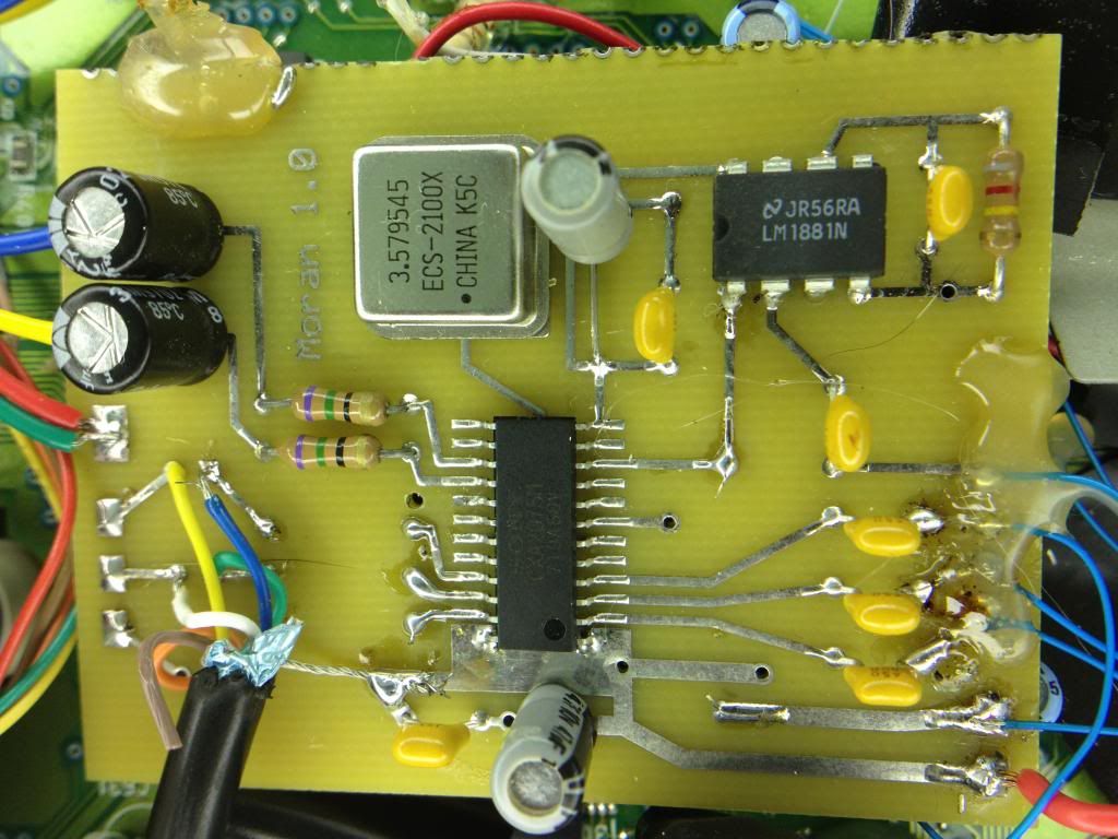
first of all here are some photos of the OLD transistor-based amp that uses c-sync , it is amped the same way as RGB
please view them fullscreen 1:1 size
 (http://s125.photobucket.com/albums/p55/restqp/PCE-7314/?action=view¤t=IMG01089-20121109-1038.jpg)
  (http://s125.photobucket.com/albums/p55/restqp/PCE-7314/?action=view¤t=IMG01088-20121109-1038.jpg)
  (http://s125.photobucket.com/albums/p55/restqp/PCE-7314/?action=view¤t=IMG01087-20121109-1038.jpg)
and here are the pics with the 7314 that uses composite and has a checkerboard pattern because of this:
 (http://s125.photobucket.com/albums/p55/restqp/PCE-7314/?action=view¤t=IMG01094-20121109-1110.jpg)
  (http://s125.photobucket.com/albums/p55/restqp/PCE-7314/?action=view¤t=IMG01093-20121109-1110.jpg)
  (http://s125.photobucket.com/albums/p55/restqp/PCE-7314/?action=view¤t=IMG01092-20121109-1110.jpg)
  (http://s125.photobucket.com/albums/p55/restqp/PCE-7314/?action=view¤t=IMG01091-20121109-1110.jpg)
the pics above are by following this diagram without the pullup parts (for now)

I assume that once an amplified c-sync signal is used with the 7314 , the quality will improve and be at least the same as the old amp...
first of all here are some photos of the OLD transistor-based amp that uses c-sync , it is amped the same way as RGB
please view them fullscreen 1:1 size
(http://s125.photobucket.com/albums/p55/restqp/PCE-7314/?action=view¤t=IMG01089-20121109-1038.jpg) (http://s125.photobucket.com/albums/p55/restqp/PCE-7314/?action=view¤t=IMG01088-20121109-1038.jpg) (http://s125.photobucket.com/albums/p55/restqp/PCE-7314/?action=view¤t=IMG01087-20121109-1038.jpg)and here are the pics with the 7314 that uses composite and has a checkerboard pattern because of this:
(http://s125.photobucket.com/albums/p55/restqp/PCE-7314/?action=view¤t=IMG01094-20121109-1110.jpg) (http://s125.photobucket.com/albums/p55/restqp/PCE-7314/?action=view¤t=IMG01093-20121109-1110.jpg) (http://s125.photobucket.com/albums/p55/restqp/PCE-7314/?action=view¤t=IMG01092-20121109-1110.jpg) (http://s125.photobucket.com/albums/p55/restqp/PCE-7314/?action=view¤t=IMG01091-20121109-1110.jpg)the pics above are by following this diagram without the pullup parts (for now)
I assume that once an amplified c-sync signal is used with the 7314 , the quality will improve and be at least the same as the old amp...
Title: Re: Universal RGB Amp PCBs - Interest check
Post by: GUTS on November 13, 2012, 09:09:24 AM
Post by: GUTS on November 13, 2012, 09:09:24 AM
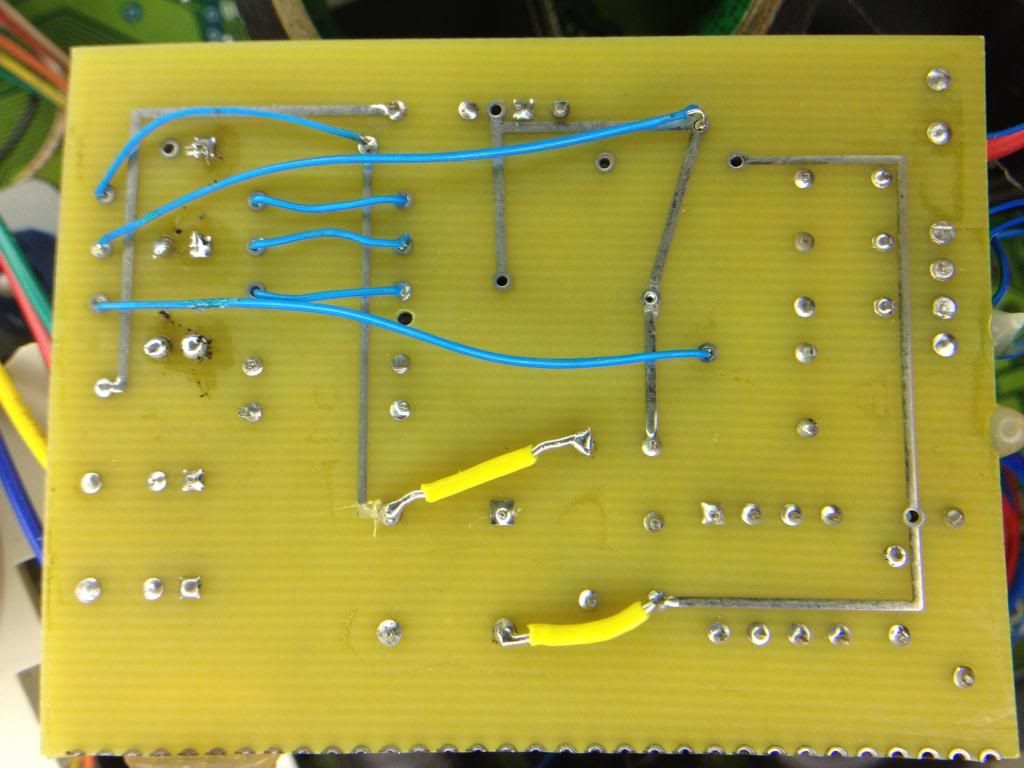
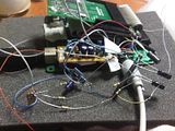
Here's a couple shots of that Turbo Grafx S-Video board, although I removed the S-Video out cable since I only use the RGB. The blue wires are mine, I think I was just routing +5, sync, and RGB to the S-Video pads.
Title: Re: Universal RGB Amp PCBs - Interest check
Post by: micro on November 15, 2012, 06:49:34 PM
Post by: micro on November 15, 2012, 06:49:34 PM
@RGB32E: Sorry, that was a typo, I always meant THS7314 by Texas Instruments.
@keropi: Nice to have a picture but it doesn't look very good (yet). ;D Without the pull-up resistors you're not using the AC-Bias Input Mode... Also, your input capacitor is way too high, and your output is DC-coupled instead of AC-coupled...?
I'm not unfamiliar with that nasty checkerboard pattern. But it's still possible to use composite video instead of composite sync without having that noise on your screen. Just use good cable in which the video wire is shielded.
Unfortunately my Turbo Duo needs a total cap replacement before I can test out the THS7314....
@GUTS: So your PCB uses a Sony CXA2075. At the RGB Output there are holes for 3x 75 Ohm resistor and 3x 220 µF capacitors but you soldered your RGB wires directly to the RGB output pins?
Title: Re: Universal RGB Amp PCBs - Interest check
Post by: GUTS on November 16, 2012, 08:37:39 AM
Post by: GUTS on November 16, 2012, 08:37:39 AM
Yeah it's been ages since I messed with it, but if I remember right it looked great coming directly off those pads so I didn't bother adding anything. I think I was out of 220uf capacitors at the time and too lazy to go to radio shack, so I just wired it up for the hell of it to see what it looked like; the picture was bright and beautiful, so I said screw and just put everything back together. I should probably add them at some point, but I was just getting into this stuff back then and didn't have the faintest clue wtf I was doing. I have a faint clue now, so one of these days I'll get around to adding the parts, ha.
Title: Re: Universal RGB Amp PCBs - Interest check
Post by: Heffa on November 29, 2012, 02:57:15 AM
Post by: Heffa on November 29, 2012, 02:57:15 AM
I would be interested in one or two of these once they are finalised :D
Title: Re: Universal RGB Amp PCBs - Interest check
Post by: BlueBMW on November 29, 2012, 11:44:52 AM
Post by: BlueBMW on November 29, 2012, 11:44:52 AM
The design change back to transistors was to make it a dual purpose YUV amp/mixer and RGB amp. We had some issues with getting the component signal just right, so another redesign is in the works.
Title: Re: Universal RGB Amp PCBs - Interest check
Post by: Heffa on November 29, 2012, 05:50:37 PM
Post by: Heffa on November 29, 2012, 05:50:37 PM
No worries, I'll gladly wait for the perfect design :)
Sent from my GT-P6800 using Tapatalk 2
Sent from my GT-P6800 using Tapatalk 2
Title: Re: Universal RGB Amp PCBs - Interest check
Post by: keropi on December 07, 2012, 07:35:27 PM
Post by: keropi on December 07, 2012, 07:35:27 PM
I did the same test with the pull ups on the RGB lines today , with the info discussed on this assembler forums thread (http://www.assemblergames.com/forums/showthread.php?42435-Schematic-for-a-*working*-PCE-rgb-amp-with-7314/page3)
 (http://s125.photobucket.com/albums/p55/restqp/?action=view¤t=IMG01254-20121207-1128.jpg)
and I got this result:

it looks the same as the old transistor-based amp to me, now all I need is a good way to build a c-sync amp, the design based on the 74HC04 discussed on the assembler thread does not work for me... using the old amp to amplify c-sync works great and I get awesome results.
micro, I will get the needed resistors/caps today to try your schematic too and see if there is a difference
(http://s125.photobucket.com/albums/p55/restqp/?action=view¤t=IMG01254-20121207-1128.jpg)and I got this result:
it looks the same as the old transistor-based amp to me, now all I need is a good way to build a c-sync amp, the design based on the 74HC04 discussed on the assembler thread does not work for me... using the old amp to amplify c-sync works great and I get awesome results.
micro, I will get the needed resistors/caps today to try your schematic too and see if there is a difference
Title: Re: Universal RGB Amp PCBs - Interest check
Post by: micro on February 05, 2013, 05:06:48 AM
Post by: micro on February 05, 2013, 05:06:48 AM
I finally had the time to replace all my PCE Duo's capacitors. Apparently the leaking caps also destroyed a via on the board which put a 4558 op-amp out of order. After installing a bypass for that broken via (the via was almost black) I finally had full sound again =)
So I could try out the THS7314 and so far I like the result:


So I could try out the THS7314 and so far I like the result:
Title: Re: Universal RGB Amp PCBs - Interest check
Post by: Heffa on February 05, 2013, 05:09:47 AM
Post by: Heffa on February 05, 2013, 05:09:47 AM
That's looking great! :)
Sent a long time ago from a Galaxy far far away using Tapatalk HD
Sent a long time ago from a Galaxy far far away using Tapatalk HD
Title: Re: Universal RGB Amp PCBs - Interest check
Post by: Heffa on May 15, 2013, 08:04:47 PM
Post by: Heffa on May 15, 2013, 08:04:47 PM
Any news on this lately? :)
Title: Re: Universal RGB Amp PCBs - Interest check
Post by: micro on May 16, 2013, 02:38:58 AM
Post by: micro on May 16, 2013, 02:38:58 AM
QuoteAny news on this lately? :)In case you're addressing me: Actually, yes :D
I've made some minor changes: The pads for RGB in and out are on the top side only now. There shouldn't be any exposed copper on the bottom side now so you could glue it onto the PCE mainboard directly without causing a short-circuit. Also there's a list on the bottom side showing the value and package of each component in case the schematic isn't in reach ;)


The size of this PCB is 34.5 mm x 18.5 mm.
A few days ago I ordered some PCB's of this design for testing purposes. If it works as intended then you can have one of those PCB's. Or I can give you the files and you can order your own PCB's :)
Title: Re: Universal RGB Amp PCBs - Interest check
Post by: RGB32E on May 16, 2013, 01:19:21 PM
Post by: RGB32E on May 16, 2013, 01:19:21 PM
Looks good! How about a PCB for a THS7374 for RGBS?
Title: Re: Universal RGB Amp PCBs - Interest check
Post by: micro on May 17, 2013, 06:22:18 AM
Post by: micro on May 17, 2013, 06:22:18 AM
I haven't tried out the THS7374 yet.
It seems the 7374 is very similar to the 7314. But in case of the PC Engine / Turbo Duo you can use composite video for synchronisation and it doesn't have to be buffered because it's already available on the (Turbo Duo's) AV out.
For which console, monitor or video input device do you need the sync signal amped or buffered?
Title: Re: Universal RGB Amp PCBs - Interest check
Post by: Heffa on May 17, 2013, 07:03:23 AM
Post by: Heffa on May 17, 2013, 07:03:23 AM
micro - I'd gladly buy one of your boards and try it out once you get them.
I'd better stock up on some SMD components though, I have no 0805 in storage :)
...also, if you are willing to share I'd love to have the files as well for further tinkering...
I'd better stock up on some SMD components though, I have no 0805 in storage :)
...also, if you are willing to share I'd love to have the files as well for further tinkering...
Title: Re: Universal RGB Amp PCBs - Interest check
Post by: RGB32E on May 18, 2013, 01:23:38 AM
Post by: RGB32E on May 18, 2013, 01:23:38 AM
RGBS output is preferred over RGBCv.
Here are some devices that require or perform better with CSYNC and not composite video:
1. Extron RGB interfaces -> No picture
2. Extron RGB switches -> No picture
3. GBS-8220 Scaler -> No picture
4. Select Sony PVM/BVM monitors -> No picture
5. NEC Multiscan monitors (XM*/ect) -> No picture as they require RGBS or RGBHV
6. XRGB upscalers -> Better PQ!
What are you using that made you think otherwise? :o I've used the THS7374 with a TG16 and it works just fine, haven't tried the 82nF/3.6M AC biasing combination yet (tried 0.1uF/5.3M).
EDIT:
7. Commodore 1084S - http://nfggames.com/forum2/index.php?topic=3387.0 (http://nfggames.com/forum2/index.php?topic=3387.0)
OP ended up switching to CSYNC from the consoles (NeoGeo modified), as the first attempt involved adding extra HW that shouldn't be required (LM1881).
Quote from: micro on May 17, 2013, 06:22:18 AM
I haven't tried out the THS7374 yet.
It seems the 7374 is very similar to the 7314. But in case of the PC Engine / Turbo Duo you can use composite video for synchronisation and it doesn't have to be buffered because it's already available on the (Turbo Duo's) AV out.
For which console, monitor or video input device do you need the sync signal amped or buffered?
Title: Re: Universal RGB Amp PCBs - Interest check
Post by: micro on May 18, 2013, 03:19:54 AM
Post by: micro on May 18, 2013, 03:19:54 AM
Well personally I'm using a Panasonic Plasma TV, a Philips CM8833 Amiga Monitor and sometimes a Sony PVM monitor. They all accept composite video for synchronizing RGB. The Panasonic TV even prefers composite video; that fucker shifts the picture to the left and cuts off a large chunk if fed with RGBS ;D
But of course I know that composite video can mess up RGB (checkerboard effect) and sound (buzzing) when it's not shielded properly.
So I don't question your love for composite sync. But the question is: For which console do you need a buffer for composite sync? And do all those devices you've listed terminate the composite sync input with 75 Ohm to GND? These are real questions because I haven't dealt with that topic before. :D
Title: Re: Universal RGB Amp PCBs - Interest check
Post by: micro on June 05, 2013, 07:51:55 AM
Post by: micro on June 05, 2013, 07:51:55 AM
The PCB's have arrived:
 (http://i.imgur.com/t2aXkml.jpg)
Heffa, have you already ordered the SMD parts? I need the SMD parts, too.
I could order all neccesary parts except for the THS7314, which is hard to come by in Germany.
Are you interested?
(http://i.imgur.com/t2aXkml.jpg)Heffa, have you already ordered the SMD parts? I need the SMD parts, too.
I could order all neccesary parts except for the THS7314, which is hard to come by in Germany.
Are you interested?
Title: Re: Universal RGB Amp PCBs - Interest check
Post by: Heffa on June 05, 2013, 08:23:29 PM
Post by: Heffa on June 05, 2013, 08:23:29 PM
Quote from: micro on June 05, 2013, 07:51:55 AMHey, it's looking good!
The PCB's have arrived:
Heffa, have you already ordered the SMD parts? I need the SMD parts, too.
I could order all neccesary parts except for the THS7314, which is hard to come by in Germany.
Are you interested?
I haven't ordered the parts yet, but I have looked for it & found most parts (inc. the THS7314) on eBay.
With the summer coming I don't have that much time, but I'm still very interested in buying one of the PCB's for when I get an evening off :D
Please send me a PM & I'll pay with PayPal if it's ok.
---
Sent a long time ago from a Galaxy far far away using Tapatalk HD
Title: Re: Universal RGB Amp PCBs - Interest check
Post by: Glossectomy on June 07, 2013, 02:19:47 PM
Post by: Glossectomy on June 07, 2013, 02:19:47 PM
I'm assuming one of these would work fine in an N64 correct? If so are you selling these or were they a preorder thing? If so what are you charging for one?
Title: Re: Universal RGB Amp PCBs - Interest check
Post by: Heffa on June 10, 2013, 09:11:44 PM
Post by: Heffa on June 10, 2013, 09:11:44 PM
Micro entrusted me with all the PCB's he didn't need himself, because he didn't have the time to sell them off one by one.
Once they arrive to me I could sell you one or two kits (including the needed components).
I'm not sure what the total will be yet, but I'll get back about that once I have the sum.
---
Sent a long time ago from a Galaxy far far away using Tapatalk HD
Once they arrive to me I could sell you one or two kits (including the needed components).
I'm not sure what the total will be yet, but I'll get back about that once I have the sum.
Quote from: Glossectomy on June 07, 2013, 02:19:47 PM
I'm assuming one of these would work fine in an N64 correct? If so are you selling these or were they a preorder thing? If so what are you charging for one?
---
Sent a long time ago from a Galaxy far far away using Tapatalk HD
Title: Re: Universal RGB Amp PCBs - Interest check
Post by: micro on June 11, 2013, 02:17:21 AM
Post by: micro on June 11, 2013, 02:17:21 AM
Quote from: Glossectomy on June 07, 2013, 02:19:47 PMYes, I'd guess so. But I don't have a suitable N64 to test.
I'm assuming one of these would work fine in an N64 correct? If so are you selling these or were they a preorder thing? If so what are you charging for one?
Actually the PCB's aren't even assembled yet.
It's true, half of the PCB's are sold to Heffa. But you can order your own PCB's if you like to.
How to get your own PCB's:
Just buy this article on ITEAD: http://imall.iteadstudio.com/open-pcb/pcb-prototyping/im120418001.html (http://imall.iteadstudio.com/open-pcb/pcb-prototyping/im120418001.html)
Options:
Thickness: 1.6 mm
Surface: HASL
E-test: 100%
Open source: as you like
Once you got an order confirmation containing your order number you can mail them the gerber files for manufacturing the PCB's. It's the ZIP file I've attached to this post. :)
Title: Re: Universal RGB Amp PCBs - Interest check
Post by: micro on June 13, 2013, 02:11:52 AM
Post by: micro on June 13, 2013, 02:11:52 AM
I've received the parts and assembled five PCB's:
 (http://i.imgur.com/cDZ2z7b.jpg)
I was struggling a little bit with soldering the big 330 uF caps. The exposed leads are really short...
While assembling the PCB's I've used this order to solder the components to the board:

I still have to test the PCB inside the PCE ;D
(http://i.imgur.com/cDZ2z7b.jpg)I was struggling a little bit with soldering the big 330 uF caps. The exposed leads are really short...
While assembling the PCB's I've used this order to solder the components to the board:
I still have to test the PCB inside the PCE ;D
Title: Re: Universal RGB Amp PCBs - Interest check
Post by: Heffa on June 13, 2013, 02:22:45 AM
Post by: Heffa on June 13, 2013, 02:22:45 AM
Looking good!
I'm hoping that I'll be able to build a couple of these myself, knowing that I have previously soldered exactly three surface mounted components- opamps in my PPA headphone amp :P
---
Sent a long time ago from a Galaxy [Tab] far far away using Tapatalk HD
I'm hoping that I'll be able to build a couple of these myself, knowing that I have previously soldered exactly three surface mounted components- opamps in my PPA headphone amp :P
---
Sent a long time ago from a Galaxy [Tab] far far away using Tapatalk HD
Title: Re: Universal RGB Amp PCBs - Interest check
Post by: vxbinaca on July 10, 2013, 06:03:13 AM
Post by: vxbinaca on July 10, 2013, 06:03:13 AM
I would be down to buy a couple of these depending on price and availability as long as they work with the following systems:
- PC Engine
- Master System
- N64
- Genesis.
I would probably be starting with the PCE first in terms of mods but I'm tooling up to mod those systems right now.
Okay so does this introduce display lag versus using transistors?
- PC Engine
- Master System
- N64
- Genesis.
I would probably be starting with the PCE first in terms of mods but I'm tooling up to mod those systems right now.
Okay so does this introduce display lag versus using transistors?
Title: Re: Universal RGB Amp PCBs - Interest check
Post by: Heffa on July 10, 2013, 06:49:07 AM
Post by: Heffa on July 10, 2013, 06:49:07 AM
Quote from: vxbinaca on July 10, 2013, 06:03:13 AMUnfortunately I have already assembled and sold all the extra boards I don't need myself... but since Micro shared the gerber files it's pretty easy for you to order a set yourself :)
I would be down to buy a couple of these
---
Sent a long time ago from a Galaxy [Tab] far far away using Tapatalk HD
Title: Re: Universal RGB Amp PCBs - Interest check
Post by: RGB32E on July 10, 2013, 07:15:45 AM
Post by: RGB32E on July 10, 2013, 07:15:45 AM
Looks slick! How is the picture quality? Does the AC-Bias input combination of 82pF/3.6M get the picture just right?
Title: Re: Universal RGB Amp PCBs - Interest check
Post by: micro on July 10, 2013, 07:13:50 PM
Post by: micro on July 10, 2013, 07:13:50 PM
One or two weeks ago I've installed one of my five THS7314 PCB's in a PCE Interface Unit. The picture looks fine, just as fine as on the pictures I posted some months ago. Maybe I can post some screenshots later.
Back then I've soldered the THS7314 on a breadboard, using 100 nF input caps and 220 uF output caps instead of 82 nF and 330 uF. That's about the only differences...
I don't know why it seems like people are using 5.1 MOhm pull-up resistors by default. I've also raised that question on the assemblergames forums but I haven't received an answer yet.
For me a 3.6 MOhm pull-up resistor seems more suited for the application. And when using a 3.6 MOhm pull-up, the value of the input cap should be 82 nF to get a cutoff frequency of 3 Hz as suggested in the datasheet :)
Title: Re: Universal RGB Amp PCBs - Interest check
Post by: RGB32E on July 11, 2013, 02:46:20 AM
Post by: RGB32E on July 11, 2013, 02:46:20 AM
Quote from: micro on July 10, 2013, 07:13:50 PM
For me a 3.6 MOhm pull-up resistor seems more suited for the application. And when using a 3.6 MOhm pull-up, the value of the input cap should be 82 nF to get a cutoff frequency of 3 Hz as suggested in the datasheet :)
To rephrase my question, what is the picture quality difference between 82nF/3.6M AC-bias input operation and 0.1uF AC-coupled input operation? Does it actually "fix" or correct anything?
EDIT:
To quote the datasheet:
QuoteThe THS7314 allowable input range is approximately 0-V to (+Vs – 1.5V) which allows for a wide input voltage
range. As such, the input dc-bias point is very flexible with the output dc-bias point being the primary factor. For
example, if the output dc-bias point is desired to be mid-rail on a 3.3-V supply, then the input dc-bias point
should be (1.65V – 290mV) /2 = 0.68V. Thus, the pull-up resistor calculates to about 3.01-MΩ resulting in
0.693V. If the output dc-bias point is desired to be 0.68-V with a 5-V power supply, then the pull-up resistor
calculates to about 5.1-MΩ.
Title: Re: Universal RGB Amp PCBs - Interest check
Post by: micro on July 11, 2013, 08:23:30 PM
Post by: micro on July 11, 2013, 08:23:30 PM
Quote from: RGB32E on July 11, 2013, 02:46:20 AMQuote from: micro on July 10, 2013, 07:13:50 PM
For me a 3.6 MOhm pull-up resistor seems more suited for the application. And when using a 3.6 MOhm pull-up, the value of the input cap should be 82 nF to get a cutoff frequency of 3 Hz as suggested in the datasheet :)
To rephrase my question, what is the picture quality difference between 82nF/3.6M AC-bias input operation and 0.1uF AC-coupled input operation? Does it actually "fix" or correct anything?
So essentially you're asking if there's a difference in picture quality between the AC-bias input mode and the sync tip clamp input mode. Because that's the input mode you get when you leave out the pull-up resistors:
Quote

To be honest I've ruled out the sync tip clamp input mode in the very beginning because to me the AC-bias input seems better suited for the RGB video signals of the PCE. There's no sync signal embedded in those RGB signals, or is it?
Also on the first page viletim suggested AC bias input mode, have a look: http://nfggames.com/forum2/index.php?topic=4822.msg31748#msg31748 (http://nfggames.com/forum2/index.php?topic=4822.msg31748#msg31748)
Quote from: RGB32E on July 11, 2013, 02:46:20 AM
EDIT:
To quote the datasheet:QuoteThe THS7314 allowable input range is approximately 0-V to (+Vs – 1.5V) which allows for a wide input voltage
range. As such, the input dc-bias point is very flexible with the output dc-bias point being the primary factor. For
example, if the output dc-bias point is desired to be mid-rail on a 3.3-V supply, then the input dc-bias point
should be (1.65V – 290mV) /2 = 0.68V. Thus, the pull-up resistor calculates to about 3.01-MΩ resulting in
0.693V. If theoutputinput dc-bias point is desired to be 0.68-V with a 5-V power supply, then the pull-up resistor
calculates to about 5.1-MΩ.
First of all, it seems there's a typo in the datasheet, see above.
See, those values in the datasheet are just for demonstration and not to be mistaken as suggested values in my opinion. The first example shows how to calculate the pull-up resistor value if your output DC-bias point should be 1.65 V = mid rail when using a 3.3 V supply. Turns out you'll need a 3.01 MOhm resistor which will effect in an input DC-bias point of 0.68 V - fine :)
Now in the second example they show you how to get the same input DC-bias point when using a 5 V supply: Then you'll need a 5.1 MOhm pull-up resistor.
What good is an input DC-bias point of 0.68 V when we're dealing with 0.7 Vpp RGB video signals?
The internal 800 kOhm pull-down resistor has a tolerance of 20% so the value could be only 640 kOhm in the worst case. With a 5.1 MOhm pull-up then you'll end up with an input DC-bias point of 0.56 V.
Now I'm not an expert in video/TV signals. But I could imagine if we're dealing with a 0.7 Vpp signal and we got an input DC-bias point of only 0.56 V the opamp's input voltage could dip into the negative values, depending on the waveform.
So I don't really understand what's the point to set the input DC-bias point THAT low with a 5.1 MOhm pull-up resistor. But it's also possible that I'm terribly mistaken, I'm open to all arguments ;D
Title: Re: Universal RGB Amp PCBs - Interest check
Post by: RGB32E on July 12, 2013, 09:49:37 AM
Post by: RGB32E on July 12, 2013, 09:49:37 AM
So have you measured the output with the 3.6M pull-up to ensure the output doesn't dip negative and cause black crush? That's the problem you're trying to fix with the pull-up, right? (That was the whole point I thought)
I picked up 3.6M 1% resistors and 82nF caps and will try this with a THS7374. I can make observations on my setup, but don't have a scope to take measurements.
I take it that your shot of cotton is similar to your assembled PCBs then. Just trying to get a pq diff.
I picked up 3.6M 1% resistors and 82nF caps and will try this with a THS7374. I can make observations on my setup, but don't have a scope to take measurements.
I take it that your shot of cotton is similar to your assembled PCBs then. Just trying to get a pq diff.
Title: Re: Universal RGB Amp PCBs - Interest check
Post by: viletim on July 12, 2013, 10:04:49 PM
Post by: viletim on July 12, 2013, 10:04:49 PM
Quote from: micro on July 11, 2013, 08:23:30 PM
What good is an input DC-bias point of 0.68 V when we're dealing with 0.7 Vpp RGB video signals?
The internal 800 kOhm pull-down resistor has a tolerance of 20% so the value could be only 640 kOhm in the worst case. With a 5.1 MOhm pull-up then you'll end up with an input DC-bias point of 0.56 V.
Now I'm not an expert in video/TV signals. But I could imagine if we're dealing with a 0.7 Vpp signal and we got an input DC-bias point of only 0.56 V the opamp's input voltage could dip into the negative values, depending on the waveform.
So I don't really understand what's the point to set the input DC-bias point THAT low with a 5.1 MOhm pull-up resistor. But it's also possible that I'm terribly mistaken, I'm open to all arguments ;D
Assuming the video is 0.7 Vpp.
One extreme - one small white dot in the middle of an otherwise black line in an otherwise black frame. DC average is pretty much 0 V.
Other extreme - Completely white frame. Each line is only white 80% of the time in reality because of the blanking interval. So DC average of the video is 0.56 V.
If the video alternates from one extreme to the other you require headroom of 0.7V above the bias point and 0.56 V below. That explains the numbers. Worst case tolerance on the internal resistor (everything else being ideal) and it will still be linear. So 5.1M will work but 3.6k is a better choice. The only reason to chose the bias point so close to ground is if you were trying to get away without the output coupling caps (and didn't care about wasted power).
Unfortunately the RGB signal the PC Engine is not 0.7 Vpp, it's actually 0.8 Vpp (I know because I bought a PC Engine a few months ago). To compensate for this I suggest attenuating the output slightly. Instead of a 75 ohm resistor in series with the output, you could use 86 ohms in series and 586 ohms to ground. This way it still looks like a 75 ohm output to the outside world. For E24 resistor values try 91 in series and 470 to ground. Not perfect but good enough - 0.67 Vpp is much better than 0.80 Vpp.
RGB32E,
Without the bias network the video will distort when it clamped to the negative rail (ground in this case). This will happen when the DC average is high and the video goes dark part way through a line. At the point it goes dark it will be clamped at ground while the input cap charges. Is the distortion significant? I don't know... It's best just to bias the amplifier properly and not worry about it.
Title: Re: Universal RGB Amp PCBs - Interest check
Post by: RGB32E on July 13, 2013, 03:22:56 AM
Post by: RGB32E on July 13, 2013, 03:22:56 AM
Quote from: viletim on July 12, 2013, 10:04:49 PM
So 5.1M will work but 3.6k is a better choice.
You mean 3.6M?
Quote from: viletim on July 12, 2013, 10:04:49 PM
Unfortunately the RGB signal the PC Engine is not 0.7 Vpp, it's actually 0.8 Vpp (I know because I bought a PC Engine a few months ago). To compensate for this I suggest attenuating the output slightly. Instead of a 75 ohm resistor in series with the output, you could use 86 ohms in series and 586 ohms to ground. This way it still looks like a 75 ohm output to the outside world. For E24 resistor values try 91 in series and 470 to ground. Not perfect but good enough - 0.67 Vpp is much better than 0.8 Vpp.
What do you mean my E24? Would the resistors to ground go before or after the series resistors? Thanks for the response!
Title: Re: Universal RGB Amp PCBs - Interest check
Post by: micro on July 13, 2013, 06:24:19 AM
Post by: micro on July 13, 2013, 06:24:19 AM
I hope viletim doesn't mind if I answer the questions... ;D
- 3.6 MOhm?
Yes, 3.6 kOhm was just a typo, definitely 3.6 MOhm.
- E24?
http://en.wikipedia.org/wiki/Preferred_number#E_series (http://en.wikipedia.org/wiki/Preferred_number#E_series)
There are different E series. E24 means there are 24 different values per decade. 91 Ohm and 470 Ohm are available in the E24 series, but 586 Ohm isn't.
- Would the resistors to ground go before or after the series resistors?
I'd say:

@viletim: 0.8 Vpp... quite interesting! On which kind of PCE did you measure the voltage? On a standard white PCE?
And thanks for explaining! :D
- 3.6 MOhm?
Yes, 3.6 kOhm was just a typo, definitely 3.6 MOhm.
- E24?
http://en.wikipedia.org/wiki/Preferred_number#E_series (http://en.wikipedia.org/wiki/Preferred_number#E_series)
There are different E series. E24 means there are 24 different values per decade. 91 Ohm and 470 Ohm are available in the E24 series, but 586 Ohm isn't.
- Would the resistors to ground go before or after the series resistors?
I'd say:
@viletim: 0.8 Vpp... quite interesting! On which kind of PCE did you measure the voltage? On a standard white PCE?
And thanks for explaining! :D
Title: Re: Universal RGB Amp PCBs - Interest check
Post by: viletim on July 13, 2013, 09:24:40 PM
Post by: viletim on July 13, 2013, 09:24:40 PM
What micro said!
Yes, the white square one.
In comparison, the NES/Famicom video chip outputs a composite video signal of 2.15 Vpp (I measured one NES and two Famicoms, it's very consistent). My guess is the little bit extra is to compensate for the losses in simple transistor driver circuits which were typically used. The emitter follower configuration has a gain of less than one in practice due to the emitter resistance (little re).
Quote from: micro on July 13, 2013, 06:24:19 AM
@viletim: 0.8 Vpp... quite interesting! On which kind of PCE did you measure the voltage? On a standard white PCE?
Yes, the white square one.
In comparison, the NES/Famicom video chip outputs a composite video signal of 2.15 Vpp (I measured one NES and two Famicoms, it's very consistent). My guess is the little bit extra is to compensate for the losses in simple transistor driver circuits which were typically used. The emitter follower configuration has a gain of less than one in practice due to the emitter resistance (little re).
Title: Re: Universal RGB Amp PCBs - Interest check
Post by: RGB32E on July 16, 2013, 02:38:40 AM
Post by: RGB32E on July 16, 2013, 02:38:40 AM
Ok, sounds good. I will pick up some 470 ohm resistors and try that out.
I'm planning to continue using the 7374 for the TG16 for simplicity (want RGBS output). Tim, do you have any comments about how best to use the THS with the CSYNC signal from the expansion port/Hu6260? I'm currently using 0.1uF on input and 220uF + 75 ohm on output. I haven't observed any issues with this configuration.
I'm planning to continue using the 7374 for the TG16 for simplicity (want RGBS output). Tim, do you have any comments about how best to use the THS with the CSYNC signal from the expansion port/Hu6260? I'm currently using 0.1uF on input and 220uF + 75 ohm on output. I haven't observed any issues with this configuration.
Title: Re: Universal RGB Amp PCBs - Interest check
Post by: BlueBMW on July 25, 2013, 03:16:53 PM
Post by: BlueBMW on July 25, 2013, 03:16:53 PM
Wow, this thread is still going?! Glad to see you guys doing some good work designing amps. Ive halfway picked up the project again and have spent some time working on a board design the last few days. Its similar to what you guys came up with but also different. Ive noticed that its hard to cover every console with a single amp design since everything seems to be a little different with regard to rgb source signals.
Anyways, heres a board design Im working on. Note, pin2 of R1-R3 is going to ground and R1-R3 are 5k pots.

Anyways, heres a board design Im working on. Note, pin2 of R1-R3 is going to ground and R1-R3 are 5k pots.
Title: Re: Universal RGB Amp PCBs - Interest check
Post by: marcus9199 on April 15, 2015, 01:14:54 AM
Post by: marcus9199 on April 15, 2015, 01:14:54 AM
I know this is an old thread, but I've got to say. I followed the suggestions made by Viletim with 3.6M ohm Pullups 82 nf caps and 91 ohm resistors in series with 470 ohm to ground. installed on my SuperGrafx and the picture is beautiful. Has there ever been a definitive answer as to what set up would be the best for PC Engine applications?
Title: Re: Universal RGB Amp PCBs - Interest check
Post by: RGB32E on April 24, 2015, 06:09:10 AM
Post by: RGB32E on April 24, 2015, 06:09:10 AM
I've had good results with Tim's suggestion as well. However, Tim has since created a product called the AV-DRIVER that works perfectly with the NEC systems! I have one of the preproduction samples and its definitely the best solution yet! It even includes a CSYNC circuit specially tailored for the Hu6260 CSYNC output. He hasn't started selling them yet, as he wants to document all of the specific applications to reduce time and effort supporting it. That said, its been many months since he started documentation so I hope he'll start selling them soon!
Title: Re: Universal RGB Amp PCBs - Interest check
Post by: panzeroceania on December 23, 2015, 03:22:35 AM
Post by: panzeroceania on December 23, 2015, 03:22:35 AM
RGB32E, I've just checked Tim's website, and still no sign of the AV Driver. Do you know if it is still in development?
Title: Re: Universal RGB Amp PCBs - Interest check
Post by: RGB32E on December 23, 2015, 03:34:02 AM
Post by: RGB32E on December 23, 2015, 03:34:02 AM
Quote from: panzeroceania on December 23, 2015, 03:22:35 AM
RGB32E, I've just checked Tim's website, and still no sign of the AV Driver. Do you know if it is still in development?
He had them manufactured over a year ago and I'd imagine he's still sitting on stock. I can't say why he doesn't put them up on his shop other than the original reason of wanting to release it with sufficient installation guides. Have you tried emailing him with an order request?
Title: Re: Universal RGB Amp PCBs - Interest check
Post by: BlockABoots on April 02, 2017, 01:08:02 AM
Post by: BlockABoots on April 02, 2017, 01:08:02 AM
Sorry to drag this post up but need a bit of help.
I bought all the compoenets to make my own PC-ENGINE RGB AMP over a year ago and just today decided to make some units up, im a bit stuck though on 2 sets of components for the R1-R3 and R4-R6 solder points on the PCB. The PCB i have is this type....

I have a bag of SMD resistors labeled as 'Multicomp, MCPWR05FT EW3604' which has '3604' labeled on the resistor itsefl and then another bag labeled as 'RES-SMD 0805-100R' which appear to have '1000' on the resistor itself. Does anyone know which resistors need to go on which R1-R3 and R4-R6 solder pads on the PCB??
I bought all the compoenets to make my own PC-ENGINE RGB AMP over a year ago and just today decided to make some units up, im a bit stuck though on 2 sets of components for the R1-R3 and R4-R6 solder points on the PCB. The PCB i have is this type....
I have a bag of SMD resistors labeled as 'Multicomp, MCPWR05FT EW3604' which has '3604' labeled on the resistor itsefl and then another bag labeled as 'RES-SMD 0805-100R' which appear to have '1000' on the resistor itself. Does anyone know which resistors need to go on which R1-R3 and R4-R6 solder pads on the PCB??